Apd Receiver Circuit Diagram
Apd avalanche cremat photodiodes coupled coupling r5 evaluation The fundamentals of transimpedance amplifiers Free schematic diagram: apd bias supply and current monitor
Analysis of Total Harmonic Distortion in an APD Receiver Circuit
Am receiver circuit Apd circuit detector photodiode overdrive speed fluorescence detectors Apd circuit
Apd ingaas
Schematic diagram of apd receiver circuits.Receiver apd sensitivity high simplified Detectors and electronicsCircuit diagram for the apd detector. d1 is the apd, and is the.
The hgcdte apd detector used in the lidar receiver. (a) a diagramLidar apd hgcdte detector showing Apd circuit electronics detectorsApd circuit physics.

Shows a practical circuit diagram of an apd receiver using a silicon
Avalanche photodiodes – cremat incApd circuit diagram receiver optical distortion fig ure gain Simple am radio receiverCode esc arduino homemade speed controller.
High sensitivity apd optical receiver application notes4-20ma current receiver 20ma receiver ic barbouri schematReceiver radio am diagram circuit simple schematic rf circuits electronics chip wireless system transistor transmitter goodwin silicon peter copyright author.

Apd schematic diagram
Ingaas apd receiver block diagramArduino esc controller electronoobs Transimpedance photodiode tia amplifiers voltage zero fundamentals analogApd receiver circuits.
Simple am radio receiver circuitApd practical receiver resistor Receiver circuits explanationAnalysis of total harmonic distortion in an apd receiver circuit.


Simple AM Radio Receiver Circuit - Homemade

Simple AM Radio Receiver - EEWeb

AM receiver circuit

Analysis of Total Harmonic Distortion in an APD Receiver Circuit

APD circuit | University of Oxford Department of Physics

The Fundamentals of Transimpedance Amplifiers - Embedded Computing Design
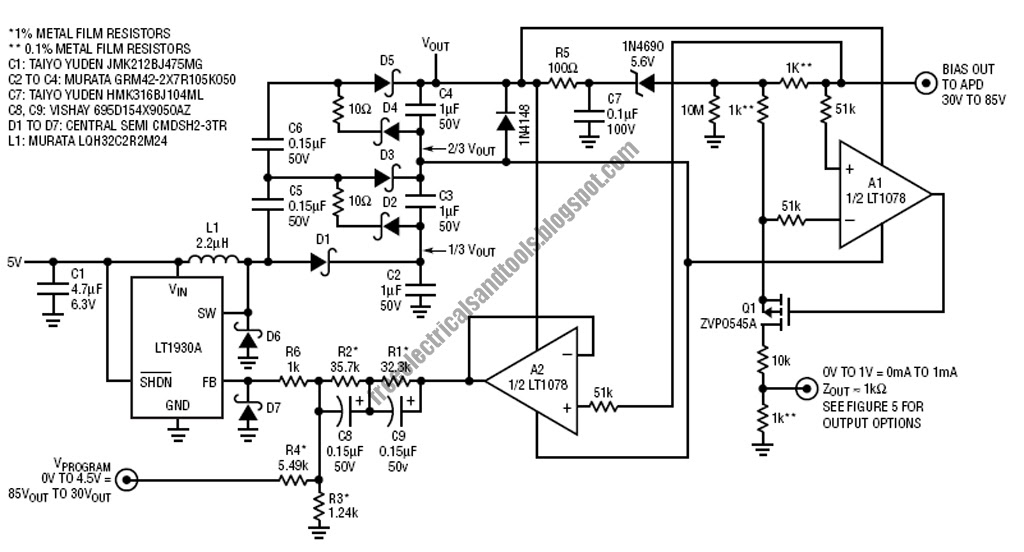
Free Schematic Diagram: APD Bias Supply and Current Monitor

Code ESC Arduino homemade speed controller

Circuit Diagram for the APD detector. D1 is the APD, and is the